Showing posts with label security. Show all posts

Using HDMI EMI for fast wireless data transfer

This story, too, begins with noise. I was browsing the radio waves with a software radio, looking for mysteries to accompany my ginger tea. I had started to notice a wide-band spiky signal on a number of frequencies that only seemed to appear indoors. Some sort of interference from electronic devices, probably. Spoiler alert, it eventually led me to broadcast a webcam picture over the radio waves... but how?

It sounds like video

The mystery deepened when I listened to how this interference sounded like as an AM signal. It reminded me of a time I mistakenly plugged our home stereo system to the Nintendo console's video output and heard a very similar buzz.

Am I possibly listening to video? Why would there be analog video transmitting on any frequency, let alone inside my home?

[Image: Oscillogram of a noisy waveform that seems to have a pulse every 10 microseconds or so.]

If we plot the signal's amplitude against time we can see that there is a strong pulse exactly 60 times per second. This could be the vertical synchronisation signal of 60 Hz video. A shorter pulse (pictured above) can be seen repeating more frequently; it could be the horizontal one. Between these pulses there is what appears to be noise. Maybe, if we use the strong pulses for synchronisation and plot the amplitude of that noise as a two-dimensional picture, we could see something?

And sure enough, when main screen turn on, we get signal:

[Image: A grainy greyscale image of what appears to be a computer desktop.]

(I've hidden the bright synchronisation signal from this picture.)

It seems to be my Raspberry Pi's desktop with weirdly distorted greyscale colours! Somehow, some part of the monitor setup is radiating it quite loudly into the aether. The frequency I'm listening to is a multiple of the monitor's pixel clock frequency.

As it turns out, this vulnerability of some monitors has been known for a long time. In 1985, van Eck demonstrated how CRT monitors can be spied on from a distance[1]; and in 2004, Markus Kuhn showed that the same still works on flat-screen monitors[2]. The image is heavily distorted, but some shapes and even bigger text can be recognisable. Sometimes this kind of eavesdropping is called "van Eck phreaking", in reference to phone phreaking.

The next thought was, could we get any more information out of these images? Is there any information about colour?

Mapping all the colours

HDMI is fully digital; there is no linear dependency between pixel values and greyscale brightness in this amplitude image. I believe the brightness in the above image is related to the number of bit transitions over my radio's sampling time (which is around 8 bit-lengths); and in HDMI, this is dependent on many things, not just the actual RGB value of the pixel. HDMI also uses multiple differential wires that all are transmitting their own picture channels side by side.

This is why I don't think it's possible easy to reconstruct a clear picture of what's being shown on the screen, let alone decode any colours.

But could the reverse be possible? Could we control this phenomenon to draw the greyscale pictures of our choice on the receiver's screen? How about sending binary data by displaying alternating pixel values on the monitor?

[Image: On the left, gradients of red, green, and blue; on the right, greyscale lines of seemingly unrelated brightness.]

My monitor uses 16-bit colours. There are "only" 65,536 different colours, so it's possible to go through all of them and see how each appears in the receiver. But it's not that simple; the bit-pattern of a HDMI pixel can actually get modified based on what came before it. And my radio isn't fast enough to even tell the bits apart anyway. What we could do is fill entire lines with one colour and average the received signal strength. We would then get a mapping for single-colour horizontal streaks (above). Assuming a long run of the same colour always produces the same bitstream, this could be good enough.

[Image: An XY plot where x goes from 0 to 65536 and Y from 0 to 1.2. A pattern seems to repeat itself every 256 values of x. Values from 16128 to 16384 are markedly higher.]

Here's the map of all the colours and their intensity in the radio receiver. (Whatever happens between 16,128 and 16,384? I don't know.)

Now, we can resample a greyscale image so that its pixels become short horizontal lines. Then, for every greyscale value find the closest matching RGB565 color in the above map. When we display this psychedelic hodge-podge of colour on the screen (on the right), enough of the above mapping seems to be preserved to produce a recognizable picture of a movie[3] on the receiver side (on the left):

[Image: On the right, a monitor shows a noisy green and blue image. On the left, another monitor shows a grainy picture of a man and the text 'Hackerman'.]

These colours are not constant in any way. If I move the antenna around, even if I turn it from vertical to horizontal, the greyscales will shift or even get inverted. If I tune the radio to another harmonic of the pixel clock frequency, the image seems to break down completely. (Are there more secrets to be unfolded in these variations?)

The binary exfiltration protocol

Now we should have enough information to be able to transmit bits. Maybe even big files and streaming data, depending on the bitrate we can achieve.

First of all, how should one bit be encoded? The absolute brightness will fluctuate depending on radio conditions. So I decided to encode bits as the brightness difference between two short horizontal lines. Positive difference means 1 and negative 0. This should stay fairly constant, unless the colours completely flip around that is.
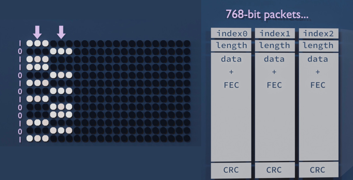
[Image: When a bit is 0, the leftmost line is darker than the rightmost line, and vice versa. These lines are used to form 768-bit packets.]

The monitor has 768 pixels vertically. This is a nice number so I designed a packet that runs vertically across the display. (This proved to be a bad decision, as we will later see.) We can stack as many packets side-by-side as the monitor width allows. A new batch of packets can be displayed in each frame, or we can repeat them over multiple frames to improve reliability.

These packets should have some metadata, at least a sequence number. Our medium is also quite noisy, so we need some kind of forward error correction. I'm using a Hamming(12,8) code which adds 4 error correction bits for every 8 bits of data. Finally, we need to add a CRC to each packet so we can make sure it arrived intact; I chose CRC16 with the polynomial 0x8005 (just because liquid-dsp provided it by default).

First results!

It was quite unbelievable, I was able to transmit a looping 64 kbps audio stream almost without any glitches, with the monitor and the receiver in the same room approximately 2 meters from each other.

Quick tip. Raw 8-bit PCM audio is a nice test format for these kinds of streaming experiments. It's straightforward to set an arbitrary bitrate by resampling the sound (with SoX for instance); there's no structure, headers, or byte order to deal with; and any packet loss, misorder, or buffer underrun is instantly audible. You can use a headerless companding algorithm like A-law to fit more dynamic range in 8 bits. Even stereo works; if you start from the wrong byte the channels will just get swapped. SoX can also play back the stream.

But can we get more? Slowly I added more samples per second, and a second audio channel. Suddenly we were at 256 kbps and still running smoothly. 200 kbps was even possible from the adjacent room, with a directional antenna 5 meters away, and with the door closed! In the same room, it worked up to around 512 kilobits per second but then hit a wall.

[Image: Info window that says HasPreamble: 1. Total: 928.5 kbps, Fresh: 853.6 kbps, Fresh (payload): 515.7 kbps.]

A tearful performance

The heavy error correction and framing adds around 60% of overhead, and we're left wit 480 bits of 'payload' per packet. If we have 39 packets per frame at 60 frames per second we should get more than a megabit per second, right? But for some reason it always caps at half a megabit.

The reason revealed itself when I noticed every other frame was often completely discarded at the CRC check. Of course; I should have thought of properly synchronising the screen update to the graphics adapter's frame update cycle (or VSYNC). This would prevent the picture information changing mid-frame, also known as tearing. But whatever options I tried with the SDL library I couldn't get the Raspberry Pi 4 to not introduce tearing.

Screen tearing appears to be an unsolved problem plaguing the Raspberry Pi 4 specifically (see this Google search). I tried another mini computer, the Asus Tinker Board R2.0, but I couldn't get the graphics drivers to work properly. I then realised it was a mistake to have the packets run from top to bottom; any horizontal tearing will cut every single packet in half! With a horizontal design only one packet per frame would suffer this fate.

A new design enables video-over-video

Packets that run horizontally across the screen indeed fix most of the packet loss. It may also help with CPU load as it improves memory access locality. I'm now able to get 1000 kbps from the monitor! What could this be used for? A live video stream, perhaps?

But the clock was ticking. I had a presentation coming up and I really wanted to amaze everyone with a video transfer demo. I quite literally got it working on the morning of the event. For simplicity, I decided to go with MJPEG, even though fancier schemes could compress way more efficiently. The packet loss issues are mostly kept at bay by repeating frames.

The data stream is "hidden" in a Windows desktop screenshot; I'm changing the colours in a way that both creates a readable bit and also looks inconspicuous when you look from far away.

Mitigations

This was a fun project but this kind of a vulnerability could, in the tinfoiliest of situations, be used for exfiltrating information out of a supposedly airgapped computer.

The issue has been alleviated in some modern display protocols. DisplayPort[4] makes use of scrambling: a pseudorandom sequence of bits is mixed with the bitstream to remove the strong clock oscillations that are so easily radiated out. This also randomizes the bitstream-to-amplitude correlation. I haven't personally tested whether it still has some kind of video in their radio interference, though. (Edit: Scrambling seems to be optionally supported by later versions of HDMI, too – but it might depend on which features exactly the two devices negotiate. How could you know if it's turned on?)

[Image: A monitor completely wrapped in tinfoil, with the text IMPRACTICAL written over it.]

I've also tried wrapping the monitor in tinfoil (very impractical) and inside a cage made out of chicken wire (it had no effect - perhaps I should have grounded it?). I can't recommend either of these.

Software considerations

This project was made possible by at least C++, Perl, SoX, ImageMagick, liquid-dsp, Dear Imgui, GLFW, turbojpeg, and v4l2! If you're a library that feels left out, please leave a comment.

If you wish to play around with video emanations, I heard there is a project called TempestSDR. For generic analog video decoding via a software radio, there is TVSharp.

References

  1. Van Eck, Wim (1985): Electromagnetic radiation from video display units: An eavesdropping risk?
  2. Kuhn, Markus (2004): Electromagnetic Eavesdropping Risks of Flat-Panel Displays
  3. KUNG FURY Official Movie [HD] (2015)
  4. Video Electronics Standards Association (2006): DisplayPort Standard, version 1.

Descrambling split-band voice inversion with deinvert

Voice inversion is a primitive method of rendering speech unintelligible to prevent eavesdropping of radio or telephone calls. I wrote about some simple ways to reverse it in a previous post. I've since written a software tool, deinvert (on Codeberg), that does all this for us. It can also descramble a slightly more advanced scrambling method called split-band inversion. Let's see how that happens behind the scenes.

Simple voice inversion

Voice inversion works by inverting the audio spectrum at a set maximum frequency called the inversion carrier. Frequencies near this carrier will thus become frequencies near zero Hz, and vice versa. The resulting audio is unintelligible, though familiar sentences can easily be recognized.

Deinvert comes with 8 preset carrier frequencies that can be activated with the -p option. These correspond to a list of carrier frequencies I found in an actual scrambler's manual, dubbed "the most commonly used inversion carriers".

The algorithm behind deinvert can be divided into three phases: 1) pre-filtering, 2) mixing, and 3) post-filtering. Mixing means multiplying the signal by an oscillation at the selected carrier frequency. This produces two sidebands, or mirrored copies of the signal, with the lower one frequency-inverted. Pre-filtering is necessary to prevent this lower sideband from aliasing when its highest components would go below zero Hertz. Post-filtering removes the upper sideband, leaving just the inverted audio. Both filters can be realized as low-pass FIR filters.

[Image: A spectrogram in four steps, where the signal is first cut at 3 kHz, then shifted up, producing two sidebands, the upper of which is then filtered out.]

This operation is its own inverse, like ROT13; by applying the same inversion again we get intelligible speech back. Indeed, deinvert can also be used as a scrambler by just running unscrambled audio through it. The same inversion carrier should be used in both directions.

Split-band inversion

The split-band scrambling method adds another carrier frequency that I call the split point. It divides the spectrum into two parts that are inverted separately and then combined, preventing ordinary inverters from fully descrambling it.

A single filter-inverter pair may already bring back the low end of the spectrum. Descrambling it fully amounts to running the inversion algorithm twice, with different settings for the filters and mixer, and adding the results together.

The problem here is to find these two frequencies. But let's take a look at an example from audio scrambled using the CML CMX264 split-band inverter (from a video by GBPPR2).

[Image: A spectrogram showing a narrow band of speech-like harmonics, but with a constant dip in the middle of the band.]

In this case the filter roll-off is clearly visible in the spectrogram and it's obvious where the split point is. The higher carrier is probably at the upper limit of the full band or slightly above it. Here the full bandwidth seems to be around 3200 Hz and the split point is at 1200 Hz. This could be initially descrambled using deinvert -f 3200 -s 1200; if the result sounds shifted up or down in frequency this could be refined accordingly.

Performance

On a single core of an i7-based laptop from 2013, deinvert processes a 44.1 kHz WAV file at 60x realtime speed (120x for simple inversion). Most of the CPU cycles are spent doing filter convolution, i.e. calculating the signal's vector dot product with the low-pass filter kernels:

[Image: A graph of the time spent in various parts of the call tree of the program, with the subtree leading to the dot product operation highlighted. It takes well over 80 % of the tree.]

For this reason deinvert has a quality setting (0 to 3) for controlling the number of samples in the convolution kernels. A filter with a shorter kernel is linearly faster to compute, but has a low roll-off and will leave more unwanted harmonics.

A quality setting of 0 turns filtering off completely, and is very fast. For simple inversion this should be fine, as long as the original doesn't contain much power above the inversion carrier. It's easy to ignore the upper sideband because of its high frequency. In split-band descrambling this leaves some nasty folded harmonics in the speech band though.

Here's a descramble of the above CMX264 split-band audio using all the different quality settings in deinvert. You will first hear it scrambled, and then descrambled with increasing quality setting.

The default quality level is 2. This should be enough for real-time descrambling of simple inversion on a Raspberry Pi 1, still leaving cycles for an FM receiver for instance:

(RasPi 1)Simple inversionSplit-band inversion
-q 016x realtime5.8x realtime
-q 16.5x realtime3.0x realtime
-q 22.8x realtime1.3x realtime
-q 31.2x realtime0.4x realtime

The memory footprint is less than four megabytes.

Future developments

There's a variant of split-band inversion where the inversion carrier changes constantly, called variable split-band. The transmitter informs the receiver about this sequence of frequencies via short bursts of data every couple of seconds or so. This data seems to be FSK, but it shall be left to another time.

I've also thought about ways to automatically estimate the inversion carrier frequency. Shifting speech up or down in frequency breaks the relationships of the harmonics. Perhaps this fact could be exploited to find a shift that would minimize this error?

Links

CTCSS fingerprinting: a method for transmitter identification

Identifying unknown radio transmitters by their signals is called radio fingerprinting. It is usually based on rise-time signatures, i.e. characteristic differences in how the transmitter frequency fluctuates at carrier power-up. Here, instead, I investigate the fingerprintability of another feature in hand-held FM transceivers, known as CTCSS or Continuous Tone-Coded Squelch System.

Motivation & data

I came across a long, losslessly compressed recording of some walkie-talkie chatter and wanted to know more about it, things like the number of participants and who's talking with who. I started writing a transcript – a fun pastime – but some voices sounded so similar I wondered if there was a way to tell them apart automatically.

[Image: Screenshot of Audacity showing an audio file over eleven hours long.]

The file comprises several thousand short transmissions as FM demodulated audio lowpass filtered at 4500 Hz. Signal quality is variable; most transmissions are crisp and clear but some are buried under noise. Passages with no signal are squelched to zero.

I considered several potentially fingerprintable features, many of them unrealistic:

  • Carrier power-up; but many transmissions were missing the very beginning because of squelch
  • Voice identification; but it would probably require pretty sophisticated algorithms (too difficult!) and longer samples
  • Mean audio power; but it's not consistent enough, as it depends on text, tone of voice, etc.
  • Maximum audio power; but it's too sensitive to peaks in FM noise

I then noticed all transmissions had a very low tone at 88.5 Hz. It turned out to be CTCSS, an inaudible signal that enables handsets to silence unwanted transmissions on the same channel. This gave me an idea inspired by mains frequency analysis: Could this tone be measured to reveal minute differences in crystal frequencies and modulation depths? Also, knowing that these were recorded using a cheap DVB-T USB stick – would it have a stable enough oscillator to produce consistent measurements?

Measurements

I used the liquid-dsp library for signal processing. It has several methods for measuring frequencies. I decided to use a phase-locked loop, or PLL; I could have also used FFT with peak interpolation.

In my fingerprinting tool, the recording is first split into single transmissions. The CTCSS tone is bandpass filtered and a PLL starts tracking it. When the PLL frequency stops fluctuating, i.e. the standard deviation is small enough, it's considered locked and its frequency is averaged over this time. The average RMS power is measured similarly.

Here's one such transmission:

[Image: A graph showing frequency and power, first fluctuating but then both stabilize for a moment, where text says 'PLL locked'. Caption says 'No, I did not copy'.]

Results

At least three clusters are clearly distinguishable by eye. Zooming in to one of the clusters reveals it's made up of several smaller clusters. Perhaps the larger clusters correspond to three different models of radios in use, and these smaller ones are the individual transmitters?

[Image: A plot of RMS power versus frequency, with dots scattered all over, but mostly concentrated in a few clusters.]

A heat map reveals even more structure:

[Image: The same clusters presented in a gradual color scheme and numbered from 1 to 12.]

It seems at least 12 clusters, i.e. potential individual transmitters, can be distinguished.

Even though most transmissions are part of some cluster, there are many outliers as well. These appear to correspond to a very noisy or very short transmission. (Could the FFT have produced better results with these?)

Use as transcription aid

My goal was to make these fingerprints useful as labels aiding transcription. This way, a human operator could easily distinguish parties of a conversation and add names or call signs accordingly.

I experimented with automated k-means clustering, but that didn't immediately produce appealing results. Then I manually assigned 12 anchor points at apparent cluster centers and had a script calculate the nearest anchor point for all transmissions. Prior to distance calculations the axes were scaled so that the data seemed uniformly distributed around these points.

This automatic labeling proved quite sensitive to errors. It could be useful when listing possible transmitters for an unknown transmission with no context; distances to previous transmissions positively mentioning call signs could be used. Instead I ended up printing the raw coordinates and colouring them with a continuous RGB scale:

[Image: A few lines from a conversation between Boa 1 and Cobra 1. Numbers in different colors are printed in front of each line.]

Here the colours make it obvious which party is talking. Call signs written in a darker shade are deduced from the context. One sentence, most probably by "Cobra 1", gets lost in noise and the RMS power measurement becomes inaccurate (463e-6). The PLL frequency is still consistent with the conversation flow, though.

Countermeasures

If CTCSS is not absolutely required in your network, i.e. there are no unwanted conversations on the frequency, then it can be disabled to prevent this type of fingerprinting. In Motorola radios this is done by setting the CTCSS code to 0. (In the menus it may also be called a PT code or Interference Eliminator code.) In many other consumer radios it's doesn't seem to be that easy.

Conclusions

CTCSS is a suitable signal for fingerprinting transmitters, reflecting minute differences in crystal frequencies and, possibly, FM modulation indices. Even a cheap receiver can recover these differences. It can be used when the signal is already FM demodulated or otherwise not suitable for more traditional rise-time fingerprinting.

Trackers leaking bank account data

A Finnish online bank used to include a US-based third-party analytics and tracking script in all of its pages. Ospi first wrote about it (in Finnish) in February 2015, and this caused a bit of a fuss.

The bank responded to users' worries by claiming that all information is collected anonymously:

[Image: A tweet by the bank, in Finnish. Translation: Our customers' personal data will not be made available to Google under any circumstances. Thanks to everyone who participated in the discussion! (2/2)]

But is it true?

As Ospi notes, a plethora of information is sent along the HTTP request for the tracker script. This includes, of course, the IP address of the user; but also the full URL the user is browsing. The bank's URLs reveal quite a bit about what the user is doing; for instance, a user planning to start a continuous savings contract will send the url continuousSavingsContractStep1.do.

I logged in to the bank (using well-known demo credentials) to record one such tracking request. The URL sent to the third party tracker contains a cleartext transaction archive code that could easily be used to match a transaction between two bank accounts, since it's identical for both users. But there's also a hex string called accountId (highlighted in red).

Remote Address: 80.***.***.***:443
Request URL:    https://www.google-analytics.com/collect?v=1&_v=j33&a=870588619&t
                =pageview&_s=1&dl=https%3A%2F%2Fonline.********.fi%2Febank%2Facco
                unt%2FinitTransactionDetails.do%3FbackLink%3Dreset%26accountId%3D
                69af881eca98b7042f18e975e00f9d49d5d5ee64%26rowNo%3D0%26type%3Dtra
                ns%26archivecode%3D20150220123456780002&ul=en-us&de=windows-1252&
                dt=Tilit%C2%A0%7C%C2%A0Verkkopankki%20%7C%20S-Pankki&sd=24-bit&sr
                =1440x900&vp=1440x150&je=1&fl=16.0%20r0&_u=QACAAQQBI~&jid=&cid=18
                39557247.1424801770&uid=&tid=UA-37407484-1&cd1=&cd2=demo_accounts
                &cd3=%2Ffi%2F&z=2098846672
Request Method: GET
Status Code:    200 OK

It's 40 hex characters long, which is 160 bits. This happens to be the length of an SHA-1 hash.

Could it really be a simple hash of the user's bank account number? Surely they would at least salt it.

Let's try!

The demo account's IBAN code is FI96 3939 0001 0006 03, but this doesn't give us the above hash. However, if we remove the country code, IBAN checksum, and all whitespaces, it turns out we have a match!

$ echo -n "FI96 3939 0001 0006 03" | shasum
dcf04c4fd3b6e29b4b43a8bf43c2713ac9be1de2  -

$ echo -n "FI9639390001000603" | shasum
3e3658e4c2802dd5c21b1c6c1ed55fc1f39c8830  -

$ echo -n "39390001000603" | shasum
69af881eca98b7042f18e975e00f9d49d5d5ee64  -

$ █

This is a BBAN format bank account number. BBAN numbers are easy to brute-force, especially if the bank is already known. I wrote the following C program, ~25 lines of code, that reversed the above hash to the correct account number in 0.5 seconds.

#include <openssl/sha.h>
#include <stdlib.h>
#include <stdio.h>
#include <string.h>

#define BBAN_LENGTH 14

int main() {
  const char target_hash[SHA_DIGEST_LENGTH] = {
    "\x69\xaf\x88\x1e\xca\x98\xb7\x04\x2f\x18"
    "\xe9\x75\xe0\x0f\x9d\x49\xd5\xd5\xee\x64"
  };
  unsigned char try_accnum[BBAN_LENGTH+1];
  unsigned char try_hash[SHA_DIGEST_LENGTH];
 
  for (int bban_office=0; bban_office < 1e4; bban_office++) {
    for (int bban_id=0; bban_id < 1e6; bban_id++) {
      snprintf((char*)try_accnum, sizeof(try_accnum),
               "3939%04d%06d", bban_office, bban_id);
      SHA1(try_accnum, BBAN_LENGTH, try_hash);
      if (memcmp(try_hash, target_hash, SHA_DIGEST_LENGTH) == 0) {
        printf("found %s\n", try_accnum);
        return EXIT_SUCCESS;
      }
    }
  }
  return EXIT_FAILURE;
}
$ gcc -lcrypto -o bban_hash bban_hash.c

$ time ./bban_hash
found 39390001000603
./bban_hash  0.42s user 0.00s system 99% cpu 0.420 total

$ █

In conclusion, the third party is provided with the user's IP address, bank account number, addresses of subpages they visit, and account numbers associated with all transactions they make. The analytics company should also have no difficulty matching the user with its own database collected from other sites, including their full name and search history.

Incidentally, this is in breach of the Guidelines on bank secrecy (PDF) by the Federation of Finnish Financial Services; "In accordance with the secrecy obligation, third parties may not even be disclosed whether a certain person is a customer of the bank" (pg 4) (sama suomeksi: "Salassapitovelvollisuus sisältää myös sen, että sivullisille ei ilmoiteta edes sitä, onko tietty henkilö pankin asiakas vai ei").

Solution

The script was eventually removed from the site, leaving the bank regretful that such a useful tool was lost.

However, alternatives do exist (like Piwik) that can be run locally, not involving a third party. Edit: The Intercept, a news website, is using non-privacy-invading metrics.

External links

The burger pager

A multinational burger chain has a restaurant nearby. One day I went there and ordered a take-away burger that was not readily available. (Exceptional circumstances; Ludum Dare was underway and I really needed fast food.) The clerk gave me a device that looked like a thick coaster, and told me I could fetch the burger from the counter when the coaster starts blinking its lights and make noises.

Of course, this device deserved a second look! (We can forget about the burger now) The device looked like a futuristic coaster with red LEDs all around it. I've blurred the text on top of it for dramatic effect.

[Image: Photo of a saucer-shaped device sitting on the edge of a table, with red LEDs all around it. It has a label sticker with a logo that is redacted from the photo.]

Several people in the restaurant were waiting for orders with their similar devices, which suggested to me this could be a pager system of some sort. Turning the receiver over, we see stickers with interesting information, including a UHF carrier frequency.

[Image: Photo of a smaller sticker on the bottom of the device, reading 'BASE ID:070 FRQ:450.2500MHZ'.]

For this kind of situations I often carry my RTL2832U-based television receiver dongle with me (the so-called rtl-sdr). Luckily this was one of those days! I couldn't help but tune in to 450.2500 MHz and see what's going on there.

[Image: Photo of a very small radio hotglued inside a Hello Kitty branded tin.]

And indeed, just before a pager went off somewhere, this burst could be heard on the frequency (FM demodulated audio):

Googling the device's model number, I found out it's using POCSAG, a common asynchronous pager protocol at 2400 bits per second. The modulation is binary FSK, which means we should be able to directly read the data from the above demodulated waveform, even by visual inspection if necessary. And here's the data.

...
10101010101010101010101010101010  preamble for bit sync
10101010101010101010101010101010
10101010101010101010101010101010
01111100110100100001010111011000  sync codeword
00101010101110101011001001001000  pager address
01111010100010011100000110010111  idle
01111010100010011100000110010111
01111010100010011100000110010111
01111010100010011100000110010111
...

There's no actual message being paged, just an 18-bit device address. It's preceded by a preamble of alternating 1's and 0's that the receiver can grab onto, and a fixed synchronization codeword that tells where the data begins. It's followed by numerous repetitions of the idle codeword.

The next question is inevitable. How much havoc would ensue if someone were to loop through all 262,144 possible addresses and send a message like this? I'll leave it as hypothetical.

Descrambling the voice inversion scrambler

Voice inversion is a method of scrambling radio conversations to render speech nearly unintelligible in ordinary radio receivers. As the name implies, it inverts the audio spectrum of a signal, making the lowest frequencies the highest and vice versa. It is not considered encryption; it's merely a sort of Pig Latin on analogue signals. Several voice scramblers utilize it, like the Selectone ST-20.

Update 09/2017: I've later released a simple descrambler tool called deinvert. You should probably try that one instead; these old scripts will be preserved here though.
[Image: A spectrogram of speech, with a cut labeled 'voice inversion' in the middle of the time axis, after which the spectrum appears to be flipped upside down.]

Voice inversion is cancelled by reapplying the inversion, i.e. inverting the audio spectrum again. Here I'll present some least-effort digital descrambling methods for the voice inversion scrambler that may be of interest to hobbyist listeners. The examples are written in Perl.

Easy

In a digitally sampled signal, whole-spectrum inversion can be achieved very easily in the time domain by multiplying every other sample by −1. This is equivalent to amplitude modulating a Nyquist frequency carrier with the signal; the upper sideband will get inverted and nicely overlaid with the lower because of symmetric folding.

Update 09/2017: I've later released a simple descrambler tool called deinvert. You should probably try that one instead; these old scripts will be preserved here though.
my $bandwidth = 4300;

my $fc = $bandwidth * 2;

# Using SoX for resampling and decoding/encoding WAV headers
open my $inf, '-|', 'sox scrambled.wav -r '.$fc.' -c 1 -t .s16 -';
open my $outf, '|-', 'sox -r '.$fc.' -c 1 -t .s16 - descrambled.wav';
my $sign = 1;

while (read $inf, my $sample, 2) {
  # Simply multiply every other sample by -1
  print $outf pack "s", (unpack "s", $sample) * $sign;
  $sign *= -1;
}

Because the whole spectrum is inverted, a sampling rate has to be chosen to (approximately) match the signal bandwidth. Slight distortion will still remain, unless the chosen Nyquist frequency perfectly matches the inverted zero frequency of the signal, or the "inversion carrier" as Selectone calls it. But speech will nevertheless be much more intelligible than in the original scrambled signal.

For example, consider a scrambled piece of audio that seems to have its highest frequency components at 4300 Hz. We would need to resample the audio at a rate of 8600 Hz and multiply every other sample by −1 to get intelligible audio.

To make things simpler, the Selectone ST-20B supports eight discrete carrier frequencies, namely 2632, 2718, 2868, 3023, 3196, 3339, 3495, and 3729 Hz, which they claim to be "the most commonly used inversion formats".

Difficult

If resampling is out of the question, we can also multiply the samples with a sine wave oscillating at the seemingly highest scrambled frequency. This will produce two sidebands; the lower will be our descrambled audio and will be conveniently at baseband. The upper sideband contains the inverted signal, but at such a high frequency it should not significantly impede intelligibility. We could improve the audio further by silencing the upper sideband using a lowpass filter.

# Sample rate
my $fs = 48000;

# Carrier frequency
my $fc = 3729;

# Optional filter - comment out to disable
my $filter = " sinc -$fc";

my $fc = freq($fc, $fs);

# Using SoX for resampling, filtering, encoding/decoding WAV headers
open my $in, '-|', 'sox scrambled.wav -c 1 -b 16 -e signed -t .raw -';
open my $out, '|-', 'sox -r '.$fs.' -c 1 -b 16 -e signed -t .raw - ' .
                    'descrambled.wav' . ($filter // "");

my $phase = 0;
while (read $in, my $sample, 2) {
  $phase += $fc;
  $phase -= 0x10000 if ($phase > 0x7FFF);

  # Multiply signal with sine wave
  print $out pack "s", (unpack "s", $sample) *
                       sin($phase / 0x7FFF * 3.14159);
}

sub freq {
  return int(.5 + $_[0] * 0x10000 / $_[1]);
}

A word about split-band scrambling

Some scramblers, like the PCD4440T, use a split-band inversion where the audio is split into two frequency bands that are then inverted separately and combined. The split frequency is user-adjustable. This is not a significant improvement; it would only require us to do the digital deinversion in two parts with different parameters.

Results

And here's a demo of what it sounds like. We begin with a (fake) scrambled message. Then the easy descramble comes on with a 1000 Hz error in the selected sampling rate; then the easy descramble with an error of 300 Hz; and the difficult method with a spot-on carrier frequency and with the upper sideband also audible. In the end, we also filter out the unwanted upper sideband.

Update 09/2017: I've later released a simple descrambler tool called deinvert. You should probably try that one instead; these old scripts will be preserved here though.

Eavesdropping on a wireless keyboard

Some time ago, I needed to find a new wireless keyboard. With the level of digital paranoia that I have, my main priority was security. But is eavesdropping a justifiable concern? How insecure would it actually be to type your passwords using an older type of wireless keyboard?

To investigate this, I bought an old Logitech iTouch PS/2 cordless keyboard at an online auction. It's dated July 2000. Back in those days, wireless desktops used the 27 MHz shortwave band; later they've largely moved to 2.4 GHz. This one happens to be of the shortwave type. They've been tapped before (pdf), but no proof-of-concept was published.

I actually disposed of the keyboard before I could photograph it, so here's a newer Logitech S510 from 2005, still using the same technology:

[Image: Photo of a black cordless QWERTY keyboard with a Logitech logo.]

Compared to modern USB wireless dongles, the receiver of the iTouch is huge. It isn't a one chip wonder either, and contains a PCB with multiple crystal oscillators and decoder ICs. Based on Google results, one of the Motorola chips is an FM receiver, which gives us a hint about the mode of transmission.

[Image: On the left, a gray box with the Logitech logo, a button labeled 'CONNECT', and a wire coming out of it, ending in two PS/2 connectors. On the right, the box opened and its PCB revealed. On the PCB there are three metal-colored crystals (16.4200 0014TC, 10.1700 0011TC3, 10.2700 HELE), two bulky components labeled LT455EW, and three microchips with Motorola logos. An array of wires goes out.]

But because eavesdropping is our goal here, I'm tossing the receiver. Afterall, the signal is well within the 11-meter band of any home receiver with an SW band. For bandwidth reasons however, I'll use my RTL2838-based television receiver dongle, which can be tuned to an arbitrary frequency and commanded to just dump the I/Q sample stream (using rtl-sdr).

The transmission is clearly visible at 27.14 MHz. Zooming closer and taking a spectrogram, the binary FM/FSK nature of the transmission becomes obvious:

[Image: Spectrogram showing a constant sinusoid and, below it, a burst of data encoded in the frequency of another sinusoid.]

The sample length of one bit indicates a bitrate of 850 bps. A reference oscillator with a digital PLL can be easily implemented in software. I assumed there's a delta encoding on top of the FSK.

One keypress produces about 85 bits of data. The bit pattern seems to always correlate with the key being pressed, so there's no encryption at all. Pressing the reassociation button doesn't change things either. Without going too much into the details of the obscure protocol, I just mapped all keys to their bit patterns, like so:

w 111111101111011111101111101101011011100111111111001111111101111011111101111101101
e 111111101111011111101111110101011011100111111111001111111101111011111101111110101
1 111111101111011111101111110110110111001111111110011111111011110111111111110110110
2 111111101111011111101111110110111111100111111111001111111101111011111101111110110
3 111111101111011111101111111010111101001111111110011111111011110111111011111110101
7 111111101111011111101111111110110110110011111111100111111110111101111111011111111
8 111111101111011111101111101110111110011111111100111111110111101111110111110111011
9 111111101111011111101111101110110101100111111111001111111101111011111101111110110
0 111111101111011111101111110110111011001111111110011111111011110111111011111101110
u 111111101111011111101111111101011110011111111100111111110111101111110111111110101
i 111111101111011111101111111101010111001111111110011111111011110111111011111111010
                                                               6,8              40% 

The bitstrings are so much correlated between keystrokes that we can calculate the Levenshtein distance of the received bitstring to all the mapped keys, find the smallest distance, and behold, we can receive text from the keyboard!

$ rtl_sdr - -f 27132000 -g 32.8 -s 96000 |\
> sox -r .raw -c 2 -r 96000 -e unsigned -b 8 - -t .raw -r 22050 - |\
> ./fm |perl deco.pl
Found 1 device(s):
  0:  Realtek, RTL2838UHIDIR, SN: 00000013

Using device 0: ezcap USB 2.0 DVB-T/DAB/FM dongle
Found Rafael Micro R820T tuner
Tuned to 27132000 Hz.
Tuner gain set to 32.800000 dB.
Reading samples in async mode...
[CAPS]0wned
█

So, when buying a keyboard for personal use, I chose one with 128-bit AES air interface encryption.

Update: This post was mostly about accomplishing this with low-level stuff readily available at home. For anyone needing a proof of concept or even decoder hardware, there's KeyKeriki.

Update #2: Due to requests, my code is here: fm.c, deco.pl. Of course it's for reference only, as it's not a working piece of software, and never will be. Oh and it's not pretty either.