
Recently I entered the era of video-capable portable music players. About time, too. My device of choice is this Action-branded Taiwanese gem from 1988 with a 5-inch CRT display (B/W), AM/FM radio, television receiver, and cassette player (mono, no rewind). It takes 9 D-sized batteries.
![[Image: A person holding a portable television-cassette player measuring roughly 30 by 30 by 20 cm. The tape compartment is open and a yellow cassette is in. The device is labeled 'BLACK/WHITE TELEVISION-RADIO-CASSETTE PLAYER' with the brand name 'ACTION'. There's a cathode-ray type display roughly 20cm across; band selector for VHF low, VHF high, UHF, FM, and AM; A tuning wheel; a volume wheel; cassette control buttons on top; and a carrying handle. In the background, there's a bigger cassette deck, and a coffee cup with drawings of sheep.]](https://blogger.googleusercontent.com/img/b/R29vZ2xl/AVvXsEhmvkTO4mGRXmXaDyMY0KEiR0YUb_9zO_iSda9cURKbsxRvor6jeBR0O699OWJdPci4nBAUZHV8k3W7YlViel9ugthHXqrCiKNhZAsqu7zi8TuqfkRRlaWMCOFsMjTAspOosLs2TgWh2mku/s1600/IMG_3900a.JPG)
The batteries inside were leaking quite a bit so I removed them in favor of a DC adapter. They actually occupied roughly half of the casing. After removing them the device looked very empty and was unbalanced because of the heavy CRT. So I had to come up with something to fill the space with.
Then it struck me: it's a perfect video terminal and tape drive for the Raspberry Pi!
The screen
The Action has a 5" black-and-white CRT display and a television tuner. The receiver is on an AN5151N integrated circuit. Now, the Raspberry Pi outputs composite video. Someone else has tried injecting composite video onto the AN5151N before, with results that didn't look very successful to me at first sight, so I just ended up buying a cheap RF modulator. It modulates a TV-frequency carrier with the composite signal, and that can be fed into the aerial input of the TV to be demodulated again.
![[Image: The cathode ray display showing the Linux console running the 'top' command. On top of it, a Raspberry Pi with two small devices connected into its USB ports and an RCA cable connected into its analog video output.]](https://blogger.googleusercontent.com/img/b/R29vZ2xl/AVvXsEgrTUx4vD5zfq2QknAVEHURmr8EigyCEO-kZdhepzjSlcqwic2bzyV1X0I_uSX39qnvRd2Yl2HBBeiwknjnnXtTtmF-RNbPn_mb80hdvDHcy9IuzzGZN7GI0o2V1PHxktkdg6OtYwhyztFQ/s1600/IMG_3917a.JPG)
Aerial input to the TV is via a miniplug, so I had to improvise an adapter for coax. It works almost perfectly, except that the CRT crops out the extremes of the display.
The battery compartment before and after refurbishing:
![[Image: Two photos showing a big battery compartment, empty in the first picture and filled with electronics in the second one, with several wires coming out.]](https://blogger.googleusercontent.com/img/b/R29vZ2xl/AVvXsEhK7HNyMLktz3pdsg_JQdUyWd5ZoQTQxXZslB8VFU9dTE4NL3-xKbMZR_hgZsZ5TtrdALsh9gD8mNYhZ1iHHaz6Ah7dEQ-lmuwpayK6KUhJLrzbYgCMafkidsE7CUrDLREbkH_nv2EGO5Y8/s1600/IMG_3921a.JPG)
The tape
The cassette player of this device is pretty simple. It does not have stereo, rewind, auto-stop, or any of the other hi-tech functions that many modern-day Walkmen have. It doesn't even stop automatically when Eject is pressed. But it works.
![[Image: The cassette player opened, showing the tape drive mechanism with several wheels connected to each other via rubber strings, and the control buttons connected to them via springs and levers.]](https://blogger.googleusercontent.com/img/b/R29vZ2xl/AVvXsEgX0QJMw52YmB_RtqpJbHGhz8mrgBxSw4zJrMC5LXwfF5WHwTZToENXSFJvBcYQ7UIX8-lawC56sMUlJxBDP4hQwv4kyUliMcvpsjiyJ9wnb34_ZWSgtUr7T1zGk6QF1daeUexgb7BcLHoT/s1600/IMG_3924a.JPG)
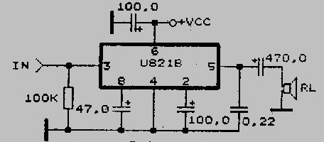
I've written a little Perl program that can write data onto cassettes and read it back using a sound card. For this project I removed the sound card step. The way I've written the data onto the tape is such that when amplified with the tape player's U821B chip, the voltage can directly be used as a binary 3v3 GPIO logic level. I wouldn't recommend this though, unless you know what you're doing, because the GPIO port is essentially a direct connection to the CPU and there's no overvoltage protecti... blast, I've just fried my RasPi!
A moment of silence. And a screenshot honouring the memory of its last words over ssh. Here, a logic "1" is low voltage, and "0" is high. A wee bit too high.
111111111111111111111111111111111111111111111111111111111111111111111111111111111111
111111111111111111111111111111111111111111111111111111111111111111111111111111111111
111111111111111111111111111111111111111111111111111111111111111111111111111111111111
111111111111111111111111111111111111111111111111111111111111111111111111111111111111
111111111111111111111111111111111111111111111111111111111111111111111111111111111111
111111111111111111111111111111111111111111111111111111111111111111111111111111111111
111111111111111111111111111111111111111111111111111111111111111111111111111111111111
111111111111111111111111111111111111111111111111111111111111111111111111111111111111
111111111111111111111111111111111111111111111111111111111111111111111111111111111111
111111111111111111111111111111111111111111111111111111111111111111111111111111111111
111111111111111111111111111111111111111111111111111111111111111111111111111111111111
111111111111111111111111111111111111111111111111111111111111111111111111111111111111
111111111111111111111111111111111111111111111111111111111111111111111111111111111111
111111111111111111111111111111111111111111111111111111111111111111111111111111111111
111111111111111111111111111111111111111111111111111111111111111111111111111111111111
111111111111111111111111111111111111111111111111111111111111111111111111111111111111
111111111111111111111111111111111111111111111111111111111111111111111111111111111111
111111111111111111111111111111111111111111111111111111111111111111111111111111111111
111111111111111111111111111111111111111111111111111111111111111111111111111111111111
111111111111111111111111111111111111111111111111111111111111111111111111111111111111
111111111111111111111111111111111111111111111111111111111111111111111111111111111111
111111111111111111111111111111111111111111111111111111111111111111111111111111111111
111111111111111111110110011Write failed: Broken pipe
$ █
Anyway, I also modified the TV's power circuitry to supply power to both the CRT and tape player at the same time, and installed a switch to silence the speaker when reading data. If it weren't for the aforementioned overvolt accident, this would now be complete. Cassettes could be used to store e.g. Vectrex games; also reading C64 cassettes will be supported.
Moral of the story: The GPIO port is not 5V tolerant! Assuming there will a second attempt some day, I'll just use a transistor to pull the GPIO pin high when there's a high on the tape. Or use a sound card.
Alternatively, you can use a current limiting resistor and/or a zener diode voltage clamp.
ReplyDeleteYou might also look at adapting some of the ham radio digital modes for reading/writing to your cassette player. They generally work in the voice spectrum and are very robust.
ReplyDeleteThe problem with tape is that tape speed can be very unstable, which renders many high-speed modes unusable. Frequency-shifting a square wave seems to be quite robust. Also, reading the data does not require any complex circuitry, just a single transistor to decide whether the bit is high or low.
Deletei'm sorry for your loss. may your RasPi rest in peace.
ReplyDeleteI have a similar tv, but without the cassette deck (which makes yours way cooler!). A 5 inch b&w screen and a radio and a mini plug ant in. How did you adapt the mini plug for coax? Is there an adapter I can purchase? Have been thinking of hooking my pi to it but wasn't sure it was possible until I found your blog post.
ReplyDeleteI built an improvised adapter myself out of coax and miniplug leads. I cut the leads near the end connectors; used a continuity meter to connect the tip of the stereo miniplug to the tip of the coax, and the sleeve of the miniplug to the shield of the coax; and left the ring unconnected. A mono miniplug would probably work even better.
DeleteFrequency-shifting a square wave.. is that functionally equivalent to Manchester encoding?
ReplyDeleteNot exactly, Manchester encoding is more akin to phase-shifting.
DeleteSo you're using FSK, but apparently with a wide enough differential, that the wow/flutter of the tape won't cause false reads. Error-correction will certainly be helpful. :)
DeleteExcellent job! I made a very similar box from an old colour tv/clock/radio but had to use a scavenged video-uhf modulator to inject via the tv's antenna socket. It's running xbmc nicely though the smaller text is only just readable.
ReplyDeleteI really like the tape storage idea :-)
I have a few similar TV/radio combinations. Some of them have a composite video input and some are RF only. Otherwise they are pretty much the same inside despite different brands on the front. I've been meaning to reverse engineer the composite video input.
ReplyDeleteHow about using the radio for receiving data to RasPi? It would be cool to load a game via radio! Awesome blog by the way.
ReplyDeleteHi! I need to do something similar for a project - mind if I ask what board you used to go from the Pis component out to RF?
ReplyDeleteCan't remember exactly - just search for "RF modulator" on eBay.
DeleteThat cassette deck is a cheapy SANYO walkman one. It's on models like Sanyo MGR-701. It is preferable adapting the AN IC input unless of modulanting signal, but well...
ReplyDeleteOh,. I also have a yellow tape! Its so curious you too have one!